Instruments and Supports
This page lets you define the label settings for Instrument and Supports.
Accessed by selecting the Annotations > Instruments and Supports node in the Settings interface.
All instruments that have defined labels in the drawing are labeled. All the labels of the instruments shall be placed as near as possible without interfering with other labels especially other instrument labels. Also, the leader line shall not interfere with the enclosure symbol of other labels.

Define the properties per the fields described below and Save the changes.
The Close icon closes the Project Settings interface, so make sure your changes are saved. You will be prompted to save them it you haven't already.
The Load Defaults icon in the main Settings interface will return the settings of the options page to their original values.
Instrument and Annotation Options
| Setting | Description |
|---|---|
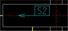
| Label Enclosure |
There are 8 types of label enclosures for
instruments. Select one of the following from the drop down list.
Once you make a selection from the list, the enclosure type will display in the bitmap image below the field. For each enclosure, there are three different types of label formats. (See below). Take some time view the different enclosure types before making the final selection. The bitmap image is updated dynamically as you move through the enclosure list. |
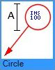
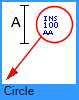
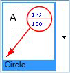
| Label Format |
There are three types of label formats for a label in an enclosure format. To select a format, click the arrow in the bitmap image below the Enclosure type. A list of bitmap images will display the different types of formats similar to the following: Click the desired bitmap to set it as the default. |
| Show Center Line | |
| Label |
Properties in this section define the display
properties of the Instrument label.
|
| Delimiter |
If the instrument label has a delimiter such as "-" in the name text, and if you want to make the label as the format of 2 or 3 lines, you need to define the delimiter. You can edit it in the Delimiter field. For example, if the instrument label is PG-100-A, and you want it to display in a 3 line format, then you will need to select the 3 line format and enter a delimiter "-" in the Delimiter field. |
| Arrow Type | Select the arrow type to use for the leader line
from the list of options.
The User Defined option displays the Select User Defined Arrow dialog letting you select an arrow symbol from a cell library. |
| Leader |

Support Annotation Options
| Setting | Description |
|---|---|
| Label Enclosure |
There are 6 types of label enclosures for
instruments. Select one of the following from the drop down list.
Click on the arrow next to the bitmap image and select an enclosure from the drop down. |
| Ortho Style Leader |
There are many orthogonal lines in the piping drawing. So it is useful to use the Non-orthogonal style leader line for distinguishing it from other orthogonal lines, which may be the pipes. The Ortho Style Leader option toggles whether a Orthogonal or Non Orthogonal leader is used. |
| Label |
Properties in this section define the display
properties of the Support label.
|
| Show Elevation Tag |
Toggles the display of the elevation tag of the pipe support. When enabled, the elevation tag will be displayed. If you checked this option, the support tag elevation will be added to the end of the support name. For Example: SP-101 EL. 459 |
| Show Symbol Mark |
Toggles the display of the symbol mark of the pipe support. When enabled, the symbol mark will be displayed. |
| Leader | |
| Arrow Type | Select the arrow type to use for the leader line from
the list of options.
The User Defined option displays the Select User Defined Arrow dialog letting you select an arrow symbol from a cell library. |
| Mode of Express |
This option determines how Support annotation is
displayed:
|
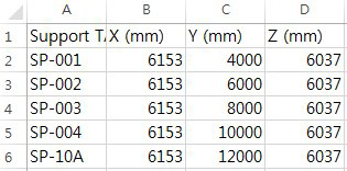
| Input CSV File |
Click the
Browse
The Clear icon will delete the current path. |


 icon next to the field to load an
existing CSV file which provides details on support tags and information.
icon next to the field to load an
existing CSV file which provides details on support tags and information.